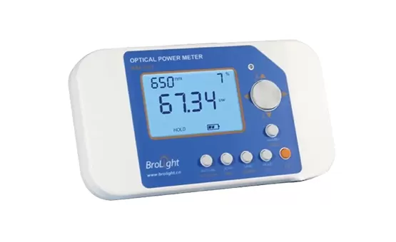
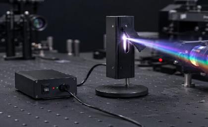
An optical power meter is used to measure the power level of light signals in fiber optic links, laser systems, optical components and photonics experiments. To use an optical power meter correctly, you need to select the right wavelength, connect the detector or fiber adapter, choose a suitable unit such as W, dBm or dB, and then read the optical power value after the signal becomes stable.
Optical power meter use is common in fiber installation, network troubleshooting, light source testing, laser power monitoring, laboratory measurement and optical component inspection. For engineers, researchers and technicians, it is one of the most practical tools for checking whether an optical signal is strong, stable and within the expected power range.
What is an Optical Power Meter and Why Is It So Important?
Encountering signal attenuation issues during fiber optic installation? You might need to check the optical power. The optical power meter is a specialized measurement tool designed to solve this problem. It is an instrument specifically used for measuring the strength of optical signals. It converts optical signals into electrical signals through a photoelectric sensor and then displays the power value in units of decibels-milliwatts (dBm) or watts (W).
The Core Value and Application Scenarios of Optical Power Meters
Optical power meters play an indispensable role in the field of optical communication. As an R&D engineer at Brolight, I have witnessed firsthand how this tool helps customers solve various practical problems.
Application Scenarios
Measurement Parameters
Importance
Optical fiber installation and maintenance
End-to-end power loss
Ensuring that network connection quality meets standards
The importance of optical power meters is reflected in several aspects. First, during optical fiber network installation, technicians need to use the optical power meter to measure the connection loss, ensuring that the loss at each joint is within the permissible range. Second, when network issues arise, comparing power values at different measurement points allows for quick location of the fault, such as whether it's due to fiber breakage or connector contamination. According to our customer feedback, correctly using an optical power meter can typically reduce troubleshooting time by more than 50%. Furthermore, the accuracy of an optical power meter directly affects the reliability of the entire communication system. A measurement error of 0.5dB can mean a 20% deviation in power calculation, which in practical applications could lead to substandard system performance. Therefore, selecting a suitable optical power meter and regular calibration are crucial.
How to Use an Optical Power Meter Step by Step
To use an optical power meter correctly, first confirm the wavelength of the light source or fiber signal. Set the same wavelength on the meter so the detector can apply the correct calibration factor. Then connect the optical fiber, detector head or optical probe to the measurement port. Choose the required unit, such as W for absolute optical power, dBm for logarithmic power level, or dB for relative loss measurement. After the reading becomes stable, record the value and compare it with the expected power range or link budget.
A typical optical power meter use process includes:
Step
Operation
Why It Matters
1
Clean the fiber connector or optical interface
Dirt or contamination can cause unstable or inaccurate readings
2
Select the correct wavelength
The detector response changes at different wavelengths
3
Connect the fiber adapter, detector head or probe
Proper alignment ensures accurate power collection
4
Choose the measurement unit
W, mW, μW, dBm and dB are used for different measurement purposes
5
Set a reference value if needed
This is useful for relative loss measurement
6
Measure the optical power
Wait until the reading becomes stable
7
Record and compare the value
Check whether the result meets the system requirement
8
Protect the detector after measurement
This helps prevent damage and contamination
For fiber optic testing, the most common wavelengths are 850 nm, 1310 nm and 1550 nm. For laser or laboratory measurement, the wavelength should match the actual light source used in the optical setup.
How Does an Optical Power Meter Work?
Curious how an optical power meter converts invisible light signals into specific numerical values? Its working principle is actually quite straightforward, the key is understanding the photoelectric conversion process. The core of an optical power meter is the photodetector. When an optical signal hits the detector, it generates a current proportional to the optical power, which is then amplified and digitized, ultimately displaying the power reading.
Workflow and Technical Details
The working process of an optical power meter can be broken down into several key steps, each involving precise photoelectric technology.
Working Phase
Function Description
Key Technology
Optical Signal Reception
Receiving the optical signal to be measured via a connector
Adapter interface, extinction ratio control
Photoelectric Conversion
Converting optical energy into electrical energy
Photodiodes (InGaAs, Si, etc.)
Signal Processing
Amplifying and filtering electrical signals
Transimpedance amplifier, low-pass filter
Data Processing
Calculating and displaying power values
Microprocessor, calibration algorithms
When an optical signal enters the optical power meter through a fiber optic connector, it first reaches the photodetector. The detector is usually made of semiconductor materials, such as indium gallium arsenide (InGaAs) for communication wavelengths or silicon (Si) for visible light. When photons hit the detector, they produce electron-hole pairs, generating a current proportional to the incident optical power. This weak current signal is then sent to a transimpedance amplifier, which converts it to a voltage signal. Because the signal is typically very weak, the amplifier must have low noise and high gain characteristics. Next, the signal undergoes filtering to remove noise interference and is then converted into a digital signal by an analog-to-digital converter. The microprocessor, based on pre-stored calibration data, converts the digital signal into the corresponding power value, considering factors such as wavelength sensitivity and linearity. Finally, the power value is displayed on the screen in units of dBm or W. It is worth mentioning that modern optical power meters usually include automatic wavelength recognition and automatic power range adjustment functions, greatly simplifying the operation process.
Optical Power Meter Units: W, mW, μW, dBm and dB
Choosing the correct optical power measurement unit is important when using an optical power meter. Different units are used for different measurement purposes. Absolute optical power is usually shown in W, mW or μW, while dBm and dB are commonly used in fiber optic communication and loss measurement.
Unit
Full Meaning
What It Shows
Common Use
W
Watt
Absolute optical power
High-power laser or light source testing
mW
Milliwatt
Absolute optical power
General optical power measurement
μW
Microwatt
Low-level optical power
Weak signal and sensor testing
dBm
Decibel-milliwatt
Power level relative to 1 mW
Fiber optic communication
dB
Decibel
Relative power difference or loss
Insertion loss and link loss testing
For example, when measuring the output of a light source, W or mW may be easier to understand. When testing a fiber optic link, dBm is often used to show the actual signal power, while dB is used to show the loss between two measurement points.
Types of Optical Power Meters and How to Choose the Right Model?
Faced with a market full of various optical power meters, how do you choose the most suitable model? This decision can indeed be difficult but by analyzing specific requirements, you can make an informed decision. Optical power meters are mainly divided into handheld, benchtop, and modular types. Selection should consider measurement range, accuracy, wavelength range, interface type, as well as specific application scenarios and budget.
Detailed Classification and Selection Guide
According to different usage scenarios and technical requirements, optical power meters can be divided into several main categories, each with its unique advantages and applicable scenarios.
Type
Features
Best Applicable Scenarios
Handheld Optical Power Meter
Portable, robust, battery-powered
Field construction, network maintenance, troubleshooting
Benchtop Optical Power Meter
High precision, multifunctional, AC-powered
Laboratories, R&D centers, manufacturing testing
Modular Optical Power Meter
Integrable, automated testing
Production testing systems, monitoring systems
PON Power Meter
Special filtering, multi-wavelength testing
Passive Optical Network installation and maintenance
When choosing an optical power meter, the first step is to clarify measurement needs. If you primarily engage in outdoor fiber wiring or network maintenance, a handheld optical power meter is the best choice. These usually have drop-proof and dust-proof characteristics, long battery life, and easy operation. Brolight's BIM series handheld power meters are specifically optimized for such applications. In laboratory or manufacturing environments, accuracy and stability are the primary considerations. Benchtop optical power meters provide higher measurement accuracy (usually within ±0.2dB), support a wider power measurement range (from -90dBm to +10dBm), and have advanced features like data storage and automatic reporting. Budget is also an important consideration. Basic handheld power meters may only cost a few thousand yuan, whereas high-precision benchtop devices can reach tens of thousands. It is recommended to prioritize measurement accuracy, reliability, and after-sales support within the budget, rather than simply pursuing low prices. Additionally, be sure to choose a model compatible with existing fiber connectors. Otherwise, additional adapters may be required.
How to Choose the Right Detector for Optical Power Meter Use
The detector is one of the most important parts of an optical power meter. If the detector does not match the wavelength or power level of the light source, the measurement result may be inaccurate. Before selecting a detector, users should confirm the wavelength range, power range, beam size, measurement speed and whether the beam is fiber-coupled or free-space.
Detector Type
Best For
Advantage
Limitation
Si photodiode detector
Visible and near-infrared light
High sensitivity and fast response
Limited wavelength range
InGaAs photodiode detector
900–1700 nm fiber communication
Suitable for telecom wavelengths
Not ideal for visible light
Thermopile detector
Laser and higher-power measurement
Handles higher optical power
Slower response
Integrating sphere detector
Divergent beam or total power measurement
Better light collection uniformity
Larger setup size
For low-power fiber or photonics measurement, a photodiode detector is usually suitable. For higher-power laser testing, a thermopile power detector is often a better choice. For divergent beams, LED output or total optical power measurement, an integrating sphere power meter can provide more stable collection conditions.
Brolight Optical Power Meter Solutions for Different Uses
Brolight provides different optical power meter solutions for fiber testing, laser measurement, laboratory research, production inspection and optical system integration. Users can choose a suitable model according to their measurement environment and optical setup.
Computer-connected measurement and automated testing
If you are not sure which optical power meter is suitable for your application, share your wavelength range, expected power level, light source type and measurement purpose with BroLight. Our team can help recommend a suitable optical power meter or detector configuration.
Conclusion
Optical power meter use is essential for fiber optic testing, laser power measurement, photonics research, light source inspection and optical system troubleshooting. By selecting the correct wavelength, using the right unit, choosing a suitable detector and following a proper measurement process, engineers can obtain more reliable optical power data.
Brolight offers handheld, USB, wireless, thermopile and integrating sphere optical power meter solutions for different wavelength ranges, power levels and application scenarios. If you need help choosing the right optical power meter, detector or measurement setup, contact BroLight and share your application requirements.
FAQ
What is an optical power meter used for?
An optical power meter is used to measure the power level of light signals in fiber optic links, laser systems, photonics instruments and optical components. It helps users check signal strength, power loss, light source output and system stability.
How do you use an optical power meter?
To use an optical power meter, select the correct wavelength, connect the fiber adapter or detector head, choose the required unit such as W, dBm or dB, and wait for the reading to become stable. The measured value can then be compared with the expected optical power range or link budget.
What unit does an optical power meter use?
An optical power meter commonly uses W, mW, μW, dBm and dB. W, mW and μW show absolute optical power. dBm shows optical power relative to 1 mW. dB is used to compare two power levels or calculate optical loss.
What is the difference between dBm and dB in optical power measurement?
dBm is an absolute power unit referenced to 1 mW. It tells you the actual optical power level. dB is a relative unit used to show the difference between two power levels, such as insertion loss or link loss.
Can an optical power meter measure laser power?
Yes, an optical power meter can measure laser power if the detector type, wavelength range and power range match the laser source. For higher-power laser measurement, a thermopile power detector is often more suitable than a standard photodiode detector.
Why should the wavelength be set before measurement?
The detector response changes at different wavelengths. Setting the correct wavelength allows the optical power meter to apply the right calibration factor and provide a more accurate reading.
What detector should I use with an optical power meter?
The detector should match the wavelength and power level of the light source. Si photodiodes are commonly used for visible and near-infrared light, InGaAs detectors are suitable for telecom wavelengths, thermopile detectors are suitable for higher-power laser measurement, and integrating sphere detectors are useful for divergent beams or total power measurement.
Why is my optical power meter reading unstable?
Unstable readings may be caused by dirty connectors, poor fiber alignment, light source fluctuation, wrong wavelength setting, detector saturation or environmental interference. Cleaning the connector, checking the setup and selecting the correct detector can help improve measurement stability.
How often should an optical power meter be calibrated?
Calibration frequency depends on the application and accuracy requirement. For routine field use, periodic calibration is recommended. For laboratory, production or quality-control measurement, calibration should follow the company’s internal quality standard or the instrument manufacturer’s recommendation.
What is the difference between an optical power meter and an optical power detector?
An optical power detector converts incoming light into an electrical signal, while an optical power meter processes that signal and displays the optical power value. In many measurement setups, the detector is the sensing part, and the meter is the reading and processing instrument.
We use cookies to offer you a better browsing experience, analyze site traffic and personalize content. By using this site, you agree to our use of cookies.
Privacy Policy
 EN
EN
 jp
jp  ko
ko  fr
fr  de
de  es
es  tr
tr  ru
ru  pt
pt  ar
ar  vi
vi