In the field of continuous laser driving, we are accustomed to the "diligence" of PID controllers—constantly measuring deviations, readjusting, like a runner forever chasing a target. However, when frequent and rapid changes in operating current are required (e.g., tunable laser scanning or multi-power-point testing), this reactive control inevitably introduces delays and compromises efficiency.
It is time to move beyond this "trial-and-error" approach.
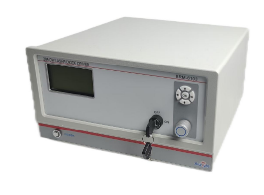
Our BRM-6103 20A CW Laser Diode Driver 20A continuous laser driver controller, building upon traditional PID feedback control, innovatively integrates Feedforward Control (FFC). Instead of "starting from scratch," it establishes a precise mathematical model of your laser diode load, "pre-knowing" exactly what output voltage is required to achieve the target current, thereby approaching the setpoint within the very first control cycle.
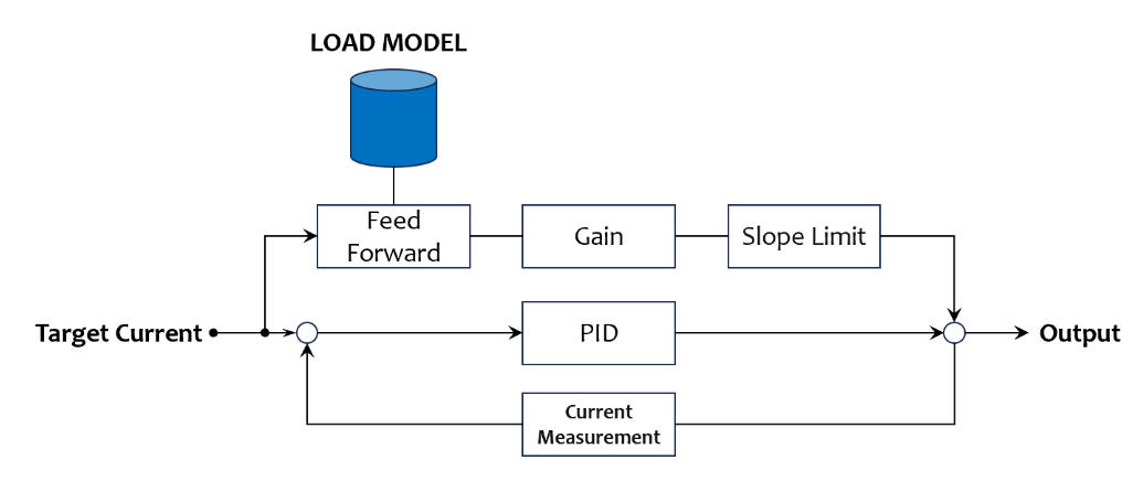
PID vs. FFC: A Contest of Responsiveness
Comparison Dimension | Traditional PID Control | BRM-6103 20A CW Laser Diode Driver Feedforward Control |
Control Logic | Reactive: Measure erroràCalculate correction àAdjust output (iterative process) | Predictive: Based on load model àDirectly compute and instantaneously apply required output |
Response Speed | Slow: Limited by iteration cycles; rise time often hundreds of milliseconds | Extremely Fast: Approaches target current within the first control cycle; measured improvement from 190ms to 100µs for nonlinear loads, and from 254ms to 650µs for linear loads |
System Performance | Inherent delays and overshoot risks | Near-instantaneous attainment with overshoot and undershoot minimized |
Why Does FFC Achieve Such a Significant Speed Advantage?
The core lies in load characterization. The BRM-6103 20A CW Laser Diode Driver runs an automated characterization routine that measures the voltage-current curve and parameterizes the characteristics of your load (e.g., a laser diode). When you set a new current value, the controller predicts and directly applies the required driving signal based on this built-in model, rather than waiting for an error to develop and then correcting it, as a PID controller would.
The following measured data, using linear and nonlinear loads, demonstrate the performance:
Control Mode | Test Graph | Data/Result |
PID | 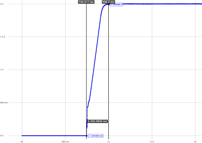
| 254ms |
FFC | 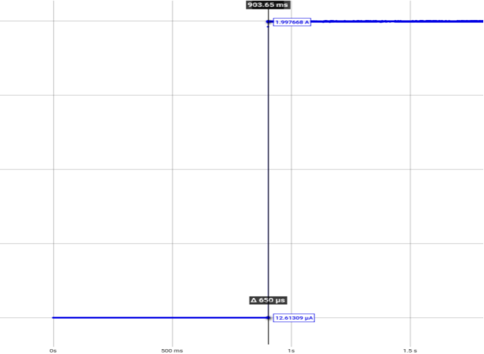
| 650µs |
Control Mode | Test Graph | Data/Result |
PID |
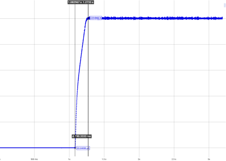
| 190ms |
FFC | 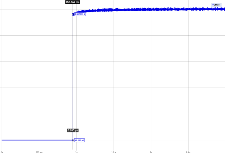
| 100µs |
As the tests demonstrate, FFC delivers a tenfold or even higher improvement in response speed, unlocking new possibilities for highly dynamic applications.
An Analogy for Understanding the Core Difference Between FFC and PID
FFC is like "driving with a navigation map"—it pre-plans the fastest route to reach your destination in one go; pure PID is like "asking for directions while driving"—you may eventually arrive, but much more slowly.
This analogy helps to quickly grasp the core differences:
Comparison Aspect | FFC (with map/navigation mode) | PID (without map/exploration mode) |
Before Departure | You have already studied the map (completed load characterization) and know the fastest and most accurate route from A to B (load model parameters). | You only know the destination (target current) but haven't seen a map. |
During the Journey | You accelerate directly along the planned route (FFC directly computes and applies the required drive output), aiming to get close to your destination quickly. | You drive while constantly asking for directions (continually measuring deviation between actual and target current), correcting your course iteratively based on feedback (PID iterative calculations), gradually approaching the target. |
Encountering a Detour/Unexpected Event (representing unknown disturbances) | Cannot handle it, because the temporary road condition isn't marked on the map (the model cannot predict sudden disturbances); you might go off course (develop deviation). At this point, you need the navigator (PID) to ask for directions in real-time and correct the route (PID compensates for residual errors). | Handles it well, because you've been continuously asking for directions (real-time feedback). Each time you encounter a detour, you can ask someone new (adjust output based on current deviation) and always find an alternative route (suppress disturbances). |
Arrival Efficiency | Extremely fast, almost direct (rise time can be reduced to 100µs). | Slower, reaching the target after repeated adjustments (rise time often hundreds of milliseconds). |
Applicability Prerequisite | The map must be accurate and up-to-date (accurate model, stable environment). If road conditions change drastically (temperature, supply voltage variations), the map becomes outdated and requires re-routing (re-characterizing the model). | No map required; inherently adaptable to changing road conditions. |
Important Note: The accuracy of navigation (FFC) is highly dependent on the accuracy of the map (the load model). If your "road conditions" (operating temperature, input voltage) are very stable and you need to change your "destination" (set current) frequently, FFC is the efficiency choice. If your "road conditions" change unpredictably or you prefer not to spend time updating the "map," then traditional PID might be more straightforward and reliable.
How Do the Two Key Parameters Work Together to Avoid Unintended Consequences?
FFC aims for a "one-step" response, but physical reality involves inertia—current changes inherently lag behind voltage changes. "Slope Limit" and "Gain" are the two key knobs that balance "ideal speed" with "physical reality." They must be adjusted in concert to prevent overshoot or oscillation.
Slope Limit: Controls "How Hard You Step on the Accelerator"
Unit: Volts per second (V/s). It directly limits the rate of change of the output voltage.
Function: It acts as the primary defense against overshoot. By allowing the voltage to "ramp up" rather than jump instantaneously ("step change"), it gives the current time to follow, preventing spikes caused by inductive effects.
Tuning Logic: Adjust the slope limit first. Start from the default value (100,000 V/s) and gradually increase it (meaning faster response) while observing the current response waveform. When you see significant overshoot beginning to appear on the waveform, revert to the previous safe value. This is the upper limit of the slope limit for that load.
Gain: Controls "How Deep You Push the Accelerator"
Unit: Percentage (%). It scales the overall output voltage calculated by the FFC.
Function: When the slope limit has been pushed to its maximum (any higher and overshoot occurs) but the rise time is still not fast enough, fine-tune the gain. Reducing the gain (e.g., to 95%) means "deliberately applying slightly less voltage," which can significantly reduce overshoot peaks at the cost of minimal steady-state accuracy.
Tuning Logic: Use only when slope limit adjustments are ineffective. Decrease it slowly in steps of 1% to 2% until the overshoot meets requirements.
Adjustment Workflow (Basic Rule)
Tuning Sequence: Load modeling → Set a reasonable slope limit (core step) → Observe response → If overshoot occurs, decrease the slope limit; if speed is insufficient and no overshoot, increase the slope limit → Only fine-tune the gain when slope limit can no longer be optimized (typically recommended to stay at ≤100%).
Why Use "PID Freeze"?
During FFC operation (i.e., the fast current establishment phase), for scenarios involving steep edges, large steps, or long cables with high inductance, it is recommended to enable the "PID Freeze" function (set to "On" or "Reset").
Reason: If the PID controller is active during a steep FFC ramp, it will sense a persistent "error" and aggressively add its own output. This can easily combine with the fast FFC command to cause a significant overshoot. Freezing the PID allows the FFC to focus on the "sprint." Once the target is approached, the PID takes over for "fine-tuning," ensuring a safe and fast response.
The Real Value and Limitations of FFC: Not a Universal Solution
The essence of FFC is "prediction" rather than "reaction." Even in continuous operation, being able to reach and maintain the set current faster and more stably is itself a significant performance leap.
However, we must candidly acknowledge its limitations, which stem directly from its core strengths—being "model-based" and an "open-loop predictor":
1. Model Dependency and Environmental Sensitivity: Significant changes in load temperature or input voltage will cause the model to become inaccurate, requiring re-characterization.
2. Inability to Handle Unknown Disturbances: Being an "open-loop" predictor, it cannot sense unexpected changes outside the model. Therefore, it must be used in conjunction with PID—FFC is responsible for the fast "attack," while PID handles continuous "correction."
3. Physical Wiring Limitations: Cable inductance and stray capacitance physically impede rapid current changes. To leverage FFC's advantages, wiring must be optimized (short and twisted pairs).
Which Continuous-Wave Scenarios Best Leverage FFC's Strengths?
1. Precision Measurements Requiring Frequent Laser Power Changes: In research and metrology, applications like spectroscopy or materials testing often require a laser to stabilize quickly at different power levels. FFC drastically shortens current settling time, enabling faster response and lower power noise during frequency tuning of continuously tunable lasers.
2. Applications Demanding High Power Stability and Immunity to Disturbances: In industrial processing or medical applications, small fluctuations in external conditions (e.g., input voltage) can affect laser power. FFC pre-compensates for external disturbances, achieving lower current ripple and higher stability compared to PID alone.
3. Equipment Driving Loads with Widely Varying Characteristics: When a single driver is used for different types of laser diodes, FFC, through load modeling, can adaptively provide an ideal initial output voltage, allowing the PID controller to "step in gently" and achieve faster response and lower overshoot across various load conditions.
Selection Reference: Is FFC Right for Your Project?
To help you quickly determine if FFC is suitable for your application, we've compiled the following selection reference table. You can check it against your specific requirements.
FFC Selection Reference Table
Your Application Scenario Characteristics | Selection Suggestion | Rationale/Judgment Criteria |
Frequent, rapid changes in set current required (e.g., tunable laser scanning, multi-point testing) | Highly Recommended | Each change is a "sprint"; FFC significantly shortens settling time. Note: Requires relatively stable ambient temperature and supply voltage, and an unchanged load. |
Extremely sensitive to current overshoot (e.g., precision medical, seed laser driver) | Use with Caution, Requires Careful Tuning | Improper FFC parameter tuning can increase overshoot risk. However, with strict adherence to the tuning procedure (prioritizing slope limit adjustment and enabling PID freeze), overshoot controllability can be superior to PID alone. |
Significant fluctuations in operating temperature or input voltage | Not Recommended, or requires frequent re-characterization | The model can become inaccurate quickly, undermining FFC advantages or even causing interference. Rely primarily on PID in such scenarios. |
Load is fixed, and set point is rarely changed (e.g., constant power output) | Limited Value; Can be omitted | PID is already sufficient in steady state. FFC's speed advantage is not utilized, adding only modeling and tuning overhead. |
Long cabling between driver and laser, or significant cable inductance | Effectiveness Limited; Wiring Must Be Optimized First | Physical limitations will diminish speed advantages and may cause ringing. Short, twisted-pair wiring is essential for FFC to be effective. |
Preference for "plug-and-play" with minimal tuning effort | Not Recommended | FFC requires additional time and expertise for modeling and parameter tuning, making it unsuitable for rapid deployment needs. |
How to Use This Selection Reference?
We suggest you evaluate your needs using the "Advantage - Prerequisite - Limitation" framework:
"The core value of FFC is to deliver a 'near-instantaneous response' for continuous-wave lasers that need frequent operating point changes, significantly boosting testing or scanning efficiency. However, realizing this advantage depends on two prerequisites: first, your operating environment (temperature and supply) must be reasonably stable; second, you need to invest a small amount of time to complete the characterization and parameter confirmation with your actual load and cabling. If your application is primarily constant-current, long-duration operation, the pure PID mode is simpler and more direct. If your system faces significant environmental variations, FFC might not be the best choice. You can quickly assess this by referring to the table above."
Experience the Shift from "Chasing" to "Anticipating" in Your Laser Control
The BRM-6103 20A CW Laser Diode Driver, by combining FFC and PID control, harnesses the ultimate speed of FFC while retaining the steady-state precision of PID. If you are facing challenges with slow response times or low scanning efficiency in continuous laser current control, FFC might be the solution you need.
Learn more about the product: https://www.ibrolight.com/search?q=BRM-6103
About Brolight
Brolight, a brand under A&P instrument(Hongkong), was established in 2012 and is headquartered in Hangzhou, China. As a China National High-Tech Enterprise specializing in the R&D, manufacturing, and sales of scientific educational instruments and optoelectronic instruments, Brolight is certified under ISO9001:2015. Leveraging over 40 years of accumulated expertise from A&P in the optoelectronics industry, Brolight is dedicated to providing high-quality photonics testing solutions for both research and industrial users.
Contact Us:
 EN
EN
 jp
jp  ko
ko  fr
fr  de
de  es
es  tr
tr  ru
ru  pt
pt  ar
ar  vi
vi